Summary
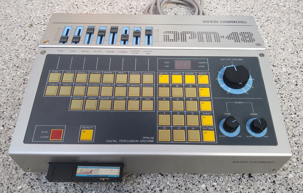
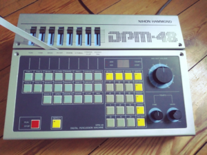
For the drum machine DPM-48 (“Digital Percussion Machine”), developed in 1984 by the Japanese manufacturer Sakata and distributed in Germany by Hammond under its own brand, an interface was to be developed that would enable the digital drum sounds stored in the machine on EPROM memory to be controlled via any MIDI-capable device.
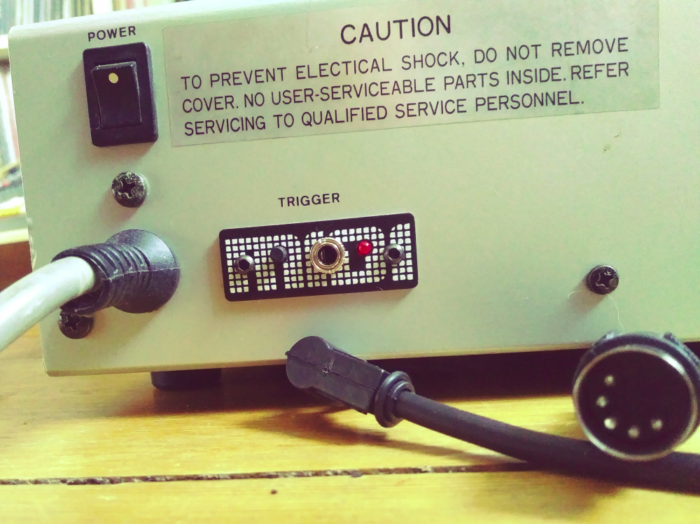
The background for the development is the limitation of the device to create and play sequences only with an inserted (optional) RAM cassette. Another possibility to control the sounds, besides the buttons on the control panel, is a so-called trigger interface. This offered the connection of an optionally available interface for the use of drum pads in addition to a real drum kit. In addition, a circuit was to be developed that would allow the factory sounds to be expanded. The selection of these extended sounds was also to be done via MIDI.
Requirements for the MIDI interface
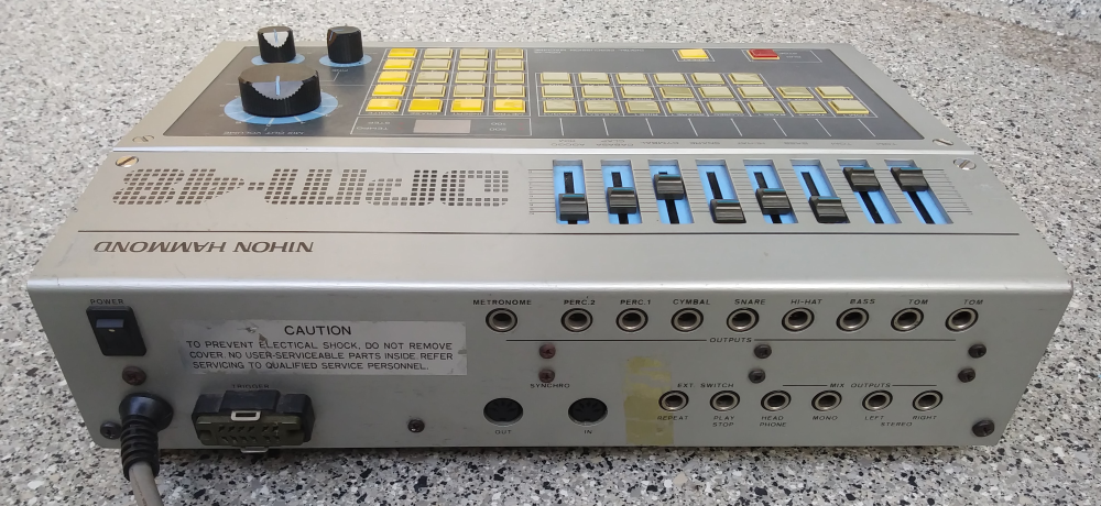
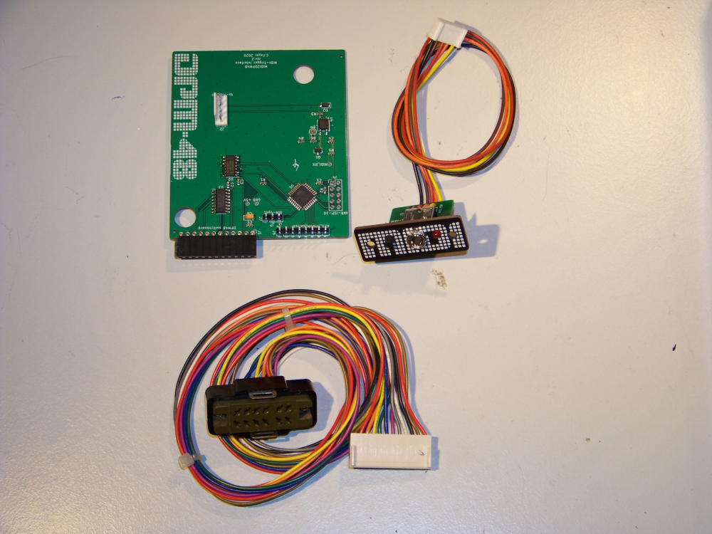
The MIDI interface to be developed is to replace the trigger socket on the back. In its place, a front panel with the MIDI connection and a user interface consisting of an LED and a button is to be attached to a UI board. This will be connected to the MIDI interface board via a multi-core cable. The MIDI interface board, which contains the microcontroller and the peripherals, is to be plugged into the microprocessor board of the DPM-48 instead of the multi-core cable of the removed trigger socket.
For space reasons, the MIDI input is designed as a 3.5 mm TRS mini jack and shall use the MIDI-TRS Type A standard.
The interface shall replace the eight trigger inputs and be able to control all 22 sounds via MIDI messages from MIDI-compatible devices. The MIDI channel shall be learnable via the button. In addition, the interface shall allow MIDI-controlled selection of extended sound banks in selected groups. The interface shall be able to be installed without altering or damaging the unit.
Block diagram
The block diagram is divided into different function blocks. Starting from the left, the MIDI input is shown; this is galvanically isolated from the Rx input (receive) of the UART in the microcontroller via an optocoupler. The firmware in the microcontroller evaluates the received MIDI messages on the set MIDI channel and selects a combination of three pad select and eight trigger lines from the matrix to control the corresponding sound. This combination is achieved by a 3-to-1 multiplexer whose output is connected to the input of a 1-to-8 demultiplexer. The pad select lines are the signals that are also used to query the button matrix of the control panel.
In addition, depending on the MIDI note number, additional address select lines (at the bottom of the picture) are switched to address one to three additional memory areas in selected EPROMs.
The pad select and trigger lines are provided by the DPM-48 together with the power supply on a 12-pin header (right in the picture).
Not shown is a button and LED that serve as a user interface and select the MIDI channel learning mode and indicate the presence of a MIDI signal.

PCB and front panel design
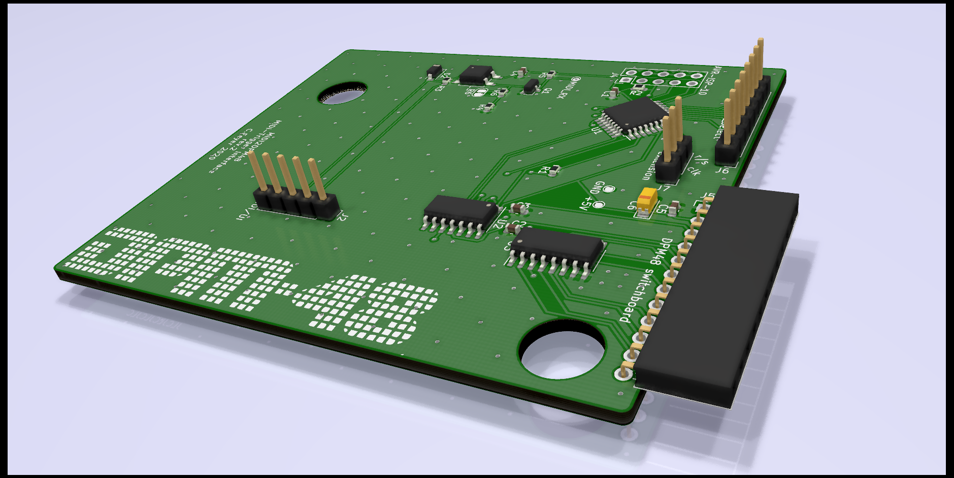
The circuit diagrams and PCB layouts for the circuit boards and the front panel were created using the free software KiCad. Two copper layers were used. The thickness of the PCBs is 1.6 mm. Except for the control button, the LED and the sockets, only SMD components were used to achieve a high packing density and to have few contact points on the underside of the board, as it was to be plugged tightly onto the existing microprocessor board of the DPM-48. For some components, the footprints had to be created first and the appropriate 3D models obtained for viewing.
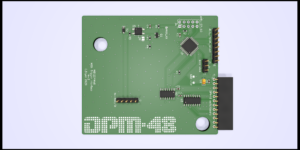
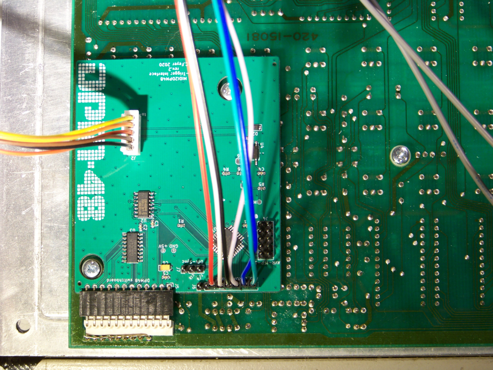
The size of the interface board is 70 x 80 mm. All SMD components are placed on the top layer. The board is connected to the main board of the DPM-48 via the angled socket connector J5. The MIDI/UI board is connected via pin header J2. Two further pin headers J6 and J7 are for connecting EPROM adapter boards. A double row pin header is used to connect to an in-system programmer for programming the microcontroller. Both layers are filled with a ground plane. Two large cut-outs leave space for the screws of the DPM-48 microprocessor board.
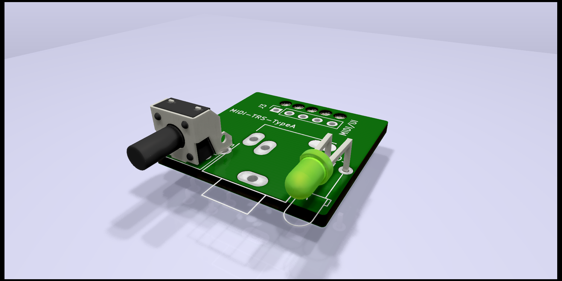
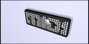
The front panel was also created with KiCad, the dimensions are 16 x 42 mm. The various drill holes were first created as footprints and saved in a component library. Both copper layers of the front panel are also filled with a ground plane. For the “MIDI” lettering, the logo of the DPM-48 was changed.
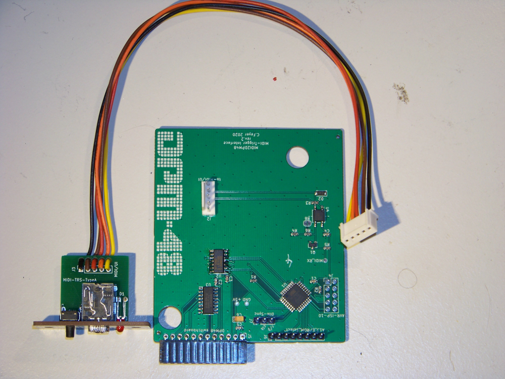
The corresponding PCB measures 25 x 25 mm and is copper-clad on one side. It carries the button, the MIDI-TRS socket and the LED. Five holes are provided as strain relief for the five-core connecting cable to the interface board, through which the cables are threaded before soldering.
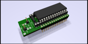
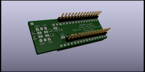
 The EPROM adapter boards allow the use of EPROMs with larger memory in the existing sockets in the drum machine. Up to three more sound banks per group are supported. This is equivalent to four times the memory of the EPROM originally used. On the bottom layer of the board there are two rows of thin pin headers that plug into the existing socket instead of the EPROM. On the top layer there is a socket into which an EPROM with two or four memory locations is plugged. The memory banks are selected from the interface board via the pins named A13 and A14.
 Firmware

The evaluation of the MIDI data and the corresponding selection of the sounds in the DPM-48 was to be done by an ATmega88 microcontroller. The firmware required for operation was written in C in the WinAVR IDE. For the MIDI and EEPROM handling of the microcontroller, open source code of the x0xb0x project was used and ported from ATmega8 to ATmega88 with the help of the application note AVR094.
The AVR Instruction Set was used to create the C code.
The microcontroller is operated with 8 MHz of the internal oscillator at +5 V operating voltage. The firmware recognises MIDI note-on messages from note C0 to A7. The sounds are played in all octaves from C0 onwards, regardless of whether they use a multi-bank EPROM.
Program flow
After initialising the hardware and the UART, the stored data for the MIDI channel and the states of the address lines are read from the sound bank extensions from the internal EEPROM of the ATmega88.
The main loop contains a request for setting a new MIDI channel. This query becomes true when the ISR(INT0_vect) detects at least a four-second push of the button. Then any MIDI note-on message can be transmitted on any channel within eight seconds. This channel is then stored in the EEPROM as a new MIDI channel for the interface in the function MIDI_channel(). In addition, the current status of the address lines of the sound bank extension is also stored. If no valid MIDI message is detected within the eight seconds in which the LED flashes and the rimshot sound is heard, the previously set channel is retained.
The MIDI handling code is also executed within the main loop. The incoming serial bytes at the UART are passed to the MUX4051() function if they are note-on messages with velocity greater than zero and have been transmitted on the set MIDI channel. This scales the received note-on message depending on the octave it was transmitted on and sets the address select lines A13 and A14 for the sound bank extension. Then, according to the note number, one of 22 possible combinations of the three pad select and eight trigger select lines is passed to the PADset() and Yselect() functions. The PADset() function controls the address lines of the 3-to-1 multiplexer, Yselect() those of the 1-to-8 demultiplexer. In addition, the latter also sets the address lines for the sound bank extension in selected groups. The function call MUXenable(ON) then triggers the corresponding sound.
Sound data and extended sound banks
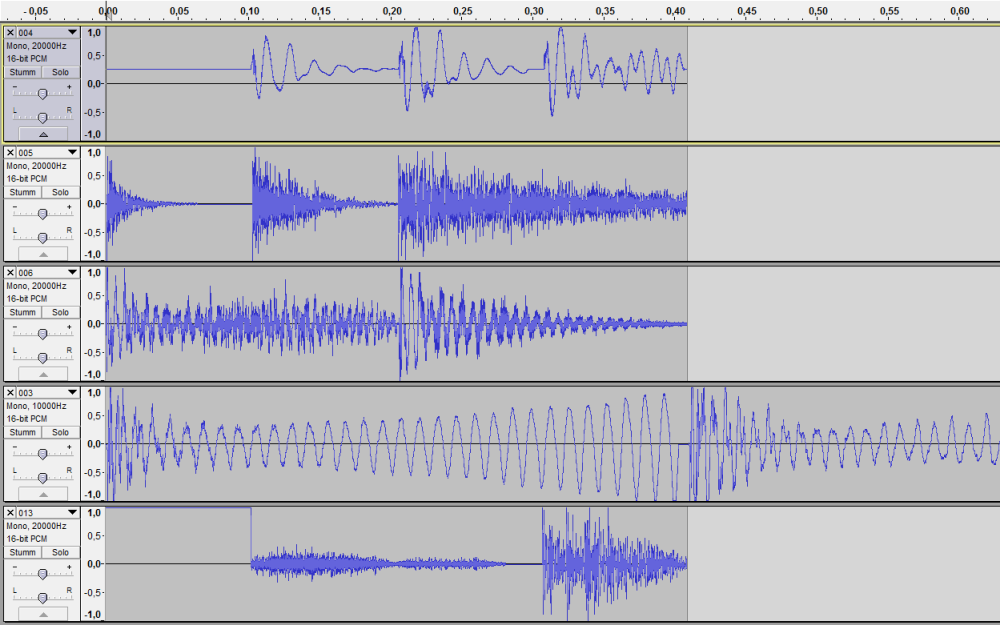
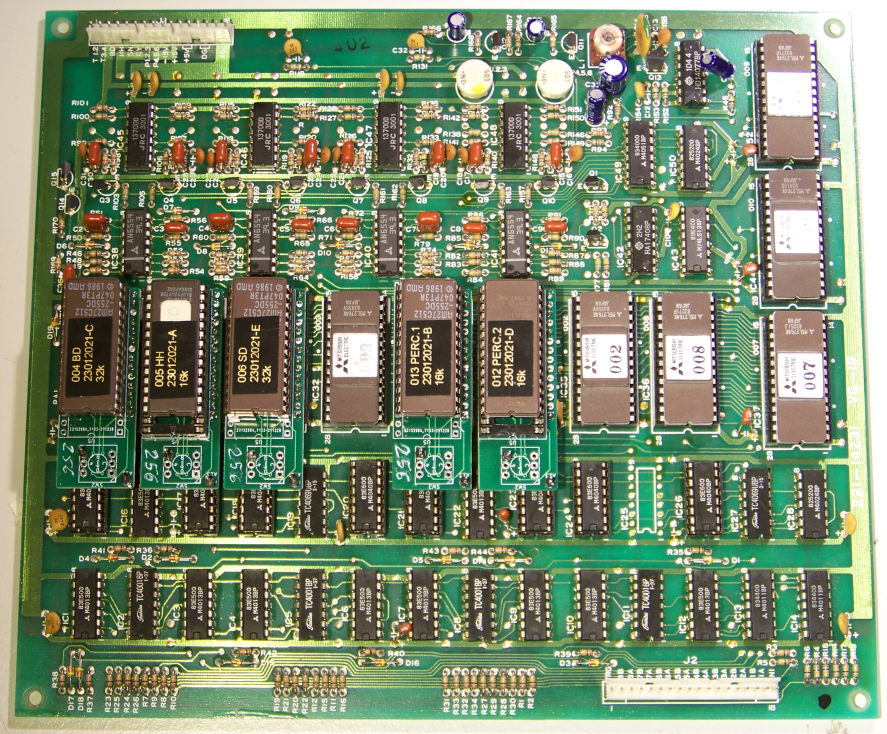
The DPM-48 drum machine uses 8-bit unsigned PCM (pulse code modulation) as audio format to play back the stored sounds. The samples of the drum and percussion sounds are stored on eleven 8 KiByte (8192 bit) EPROMs of type 2764.
For analysis, the individual EPROMs were taken out of the drum machine and read into the PC with an EPROM programmer. The individual samples are between 2 KiByte, 4 KiByte and 16 KiByte in size. With the sampling rate of 20 kHz used, this results in sample lengths between approx. 102 ms, 204 ms and 819 ms. The two TOM groups are sampled at 10 kHz and result in approximately 409 ms long sounds.
The figure below shows the imported data of each EPROM in an audio editor.
Each group has an 8-bit DAC (digital-to-analogue converter) consisting of operational amplifiers in an inverting summing circuit with subsequent re-inverting. Subsequently, each group has a VCA that is opened by an analogue envelope. The envelope is used for some identical samples with different intensity (e.g. for SNARE 1 and SNARE 2 and for RIDE 1 and RIDE 2).
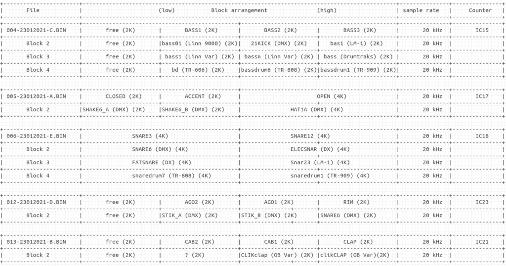
 To expand the sound banks, new data was created for selected EPROMs. The arrangement of the data is according to the original data. EPROMS with two and four sound banks were prepared. The lowest 8 KiByte block in the memory of the respective EPROM contains the original data of the EPROM of the respective group. New samples are arranged in the next higher block or blocks. In the case of the digital drum machines (Linn LM-1 and 9000, Oberheim DMX and DX and Sequential Circuits Drumtraks), the data for this comes from their EPROM data and was converted from the companded (mu-law) data format to 8-bit unsigned PCM. The samples of the analogue drum machines (Roland TR-606, TR-808, TR-909) were imported as .wav files, cut and converted.
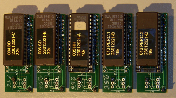
The figure shows the new arrangement in the memory of the 16 or 32 KiByte EPROMs. For the groups “HI-HAT”, “PERCUSSION 1” and “PERCUSSION 2” another bank was created, for the groups “BASS” and “SNARE” three more banks were created.
 The data was burnt onto EPROMs of type 27128 or 27256 with the programmer and the viewing windows were taped shut with lightproof labels to prevent accidental erasure. The EPROMs were inserted into five prepared adapter boards.
Installation of the interface and sound extensions
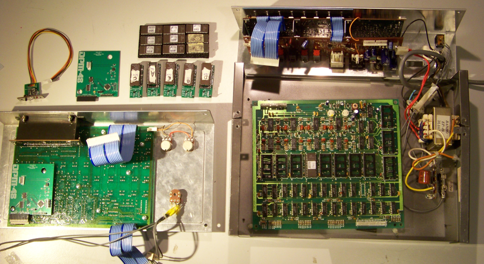
The assembled and tested boards were then installed in the DPM-48. After opening the unit and disconnecting the ribbon cables, the lid, back and bottom were separated. The trigger socket at the back was removed and the MIDI/UI board with the front panel was installed in its place. The EPROMS of the groups that were to receive an extension of the sound bank were removed and replaced by the adapter boards. The interface board was plugged onto the white 12-pin header of the DPM-48 processor board and secured on the underside with double-sided foam tape. The five-wire cable to the MIDI/UI board was plugged into J2 and the A13 and A14 connections of the EPROM adapter boards were connected to J6 and J7 according to the configuration of the firmware.
Conclusion
Once the MIDI interface has been installed in the DPM-48 drum machine, the individual sounds can be triggered via a connected MIDI keyboard, starting at note C0. In the higher octaves at note C2, C4 or C6, the extended sound banks can be played. The learning mode for the MIDI channel works as desired.
In another test, a MIDI sequencer was used to control the sounds in the DPM-48 on several tracks. Even at higher tempo and many simultaneous notes, the interface works as desired.
The interface could be installed without any changes or damage to the unit. All interventions are reversible.
By installing the developed MIDI interface, the limitations of the DPM-48 could be circumvented. In addition, the sound palette was enlarged by extending the sound banks.
A further development of the interface could provide eight independently adjustable clock signals via MIDI CC messages. These would then be connected to the binary counters of the respective group instead of the fixed sample rates and could thus enable the tuning of the sounds.
Demonstration
Triggering with MIDI-Keyboard
Sequencing with MIDI-Sequencer
Project report
In german Projektbericht-BI119_CFeyer